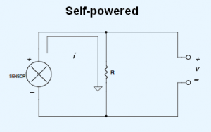
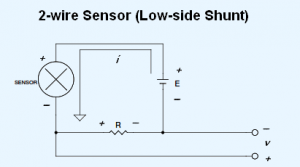
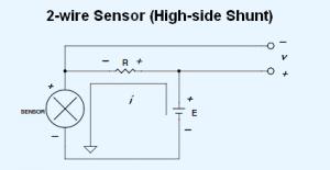
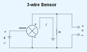
It seems that at least one 4-20 mA (milliamp) measurement is required by our typical customer, and the way to do it is a constant source of confusion for many. So I thought I’d zero in on the various 4-20 mA current loop configurations and elaborate on the specifics that you need to know to make a successful measurement. The following discussion is ordered from the most to least common configuration, and I hope to cover all those that I have encountered in customer applications. If yours isn’t included, please use the comments section to fill me in.
4-20 mA Current Loop Basics
Sensors or other devices with a 4-20 mA current loop output are extremely common in industrial measurement and control applications. They are easy to deploy, have wide power supply requirements, generate a low noise output, and can be transmitted without loss over great distances. We encounter them all the time in both process control and basic measurement data logger and data acquisition applications.
The idea behind 4-20 mA current loop operation is that the sensor draws current from its power source in direct proportion to the mechanical property it measures. Take the example of a 100 psi sensor with a current loop output. With 0 psi applied, the sensor draws 4 mA from its power source. With 100 psi applied the sensor draws 20 mA. At 50 psi the sensor draws 12 mA and so on. The relationship of mechanical property measurement to current output is almost always linear, allowing the resulting current loop data to be scaled with a simple mx+b formula to reveal more useful measurements scaled into engineering units.
How you actually measure the 4-20 mA current loop signal is a function of the sensor’s architecture and the capabilities of the instrument you’ll use for the measurement.
Terminology
So that my discussion translates well across the various kinds of 4-20 mA current loop configurations, I’ve opted to standardize the terminology I use to describe each. Here’s an overview:
“E” (dc excitation)
Most configurations that follow will show a DC voltage excitation source that I denote as “E”. Many who use current loop sensors for the first time are surprised to learn that they need to supply this excitation source. Nonetheless, unless the sensor is self-powered (i.e. AC line powered) an external dc source is required. The good news is that this can sometimes be supplied by the instrument, and the range of acceptable values is usually very wide, typically 10-24 V dc.
“R” (shunt resistor)
Here’s a bit of trivia for you: No instruments measure current directly. They all do it indirectly by measuring the voltage dropped across a resistor of known value, and then they use Ohm’s Law to calculate actual current. The resistor is referred to as a “shunt”, is absolutely required to make a current measurement, and is either supplied externally to, or built into the measuring instrument. For clarity, I assume that it’s supplied externally.
“i” (current loop value ranging from 4-20 mA)
This is the 4-20 mA current signal generated by the sensor. Note that some sensors may draw 0-20 mA and even other values, but the vast majority of them use the 4-20 mA convention.
“v” (shunt voltage that’s proportional to current)
This is the voltage actually measured by the instrument. Since our industry has standardized on a shunt value of 250 Ohms, “v” will range between 1 and 5 volts for a 4-20 mA current loop signal (v=i * resistance). Note that shunt resistor value is arbitrary as long as it’s known. You also need to ensure that it doesn’t burden the loop, so lower values are better than higher. Yes, I mean lower. Remember that we’re working with current, not voltage, so the rules are inverted. Just as infinitely-high resistor loads work well for a voltage source, you can take the load all the way to zero Ohms for a current source without consequence.
Self-powered Sensors
 I promised to order these configurations from most to least common, and the self-powered sensor just noses out the first runner up. Self-powered sensors are those that, well, power themselves. The sensor may have an integral ac power supply, thereby negating the need for an external DC power source. Or it may not be a sensor at all. It could be an output from a PLC or other source that is internally powered.
2-wire Sensors (Low-side Shunt)
 Okay, this can get confusing for first-time 4-20 mA current loop users. Yes, it is possible to both power the sensor and measure the current it draws over the same two wires. In the 2-wire examples shown here, only two wires connect the sensor to its power supply, and the sensor draws current from it in direct proportion to the mechanical property that it measures. As current changes, the voltage developed across resistor R will change, thus providing a signal that’s suitable to connect to a measuring instrument like a data logger or data acquisition system.
In most situations, care should be taken to place the resistor in the low-side of the loop as shown here, as opposed to the high-side. Doing so will allow non-isolated instruments to make the measurement. In the next section, I’ll deal with a high-side shunt placement and discuss these cautions in more detail.
2-wire Sensors (High-side Shunt)
 This configuration is almost exactly like the low-side, 2-wire approach, but it places the shunt resistor in the high-side of the loop. Note that while the voltage across the resistor is proportional to the current drawn by the sensor (just like the low-side approach), there is also a common mode voltage (CMV) present on either side to ground. On one side to ground the CMV is equal to the supply voltage. On the other side to ground it’s equal to the supply voltage, less the voltage dropped by the resistor (v). The presence of the CMVs places conditions on the instrument that you use to measure v. Specially, the instrument needs to have an isolated front end so it can float to the level of the CMV and still successfully make the measurement. Try this with a non-isolated, single-ended instrument and you will short-circuit the sensor to ground. A non-isolated differential instrument will either saturate or provide erroneous results.
3-wire Sensors
 Three-wire sensors with a process current output have a separate wire for ground, signal (4-20 mA), and the power supply. This configuration is the easiest for current loop beginners to grasp, one input for power and a second for the current loop with a common ground. The primary advantage of a 3-wire sensor over its 2-wire counterpart is its ability to drive higher resistive loads. Resistors drop voltage for any given current in direct proportion to their resistance value. Holding current constant, higher resistances drop more voltage. Turning back to the 2-wire sensor and holding current constant, as the shunt resistance increases the voltage drop across the sensor also increases. You might reach a point where the voltage dropped by the shunt lowers the voltage drop across the sensor below the minimum required for it to operate properly.
We had a customer whose 2-wire current loop measurements functioned beautifully until loop current reached about 18 mA, at which point everything went haywire. Upon close examination, we determined that the supply voltage she used was too low by at least 0.56-V. She needed 2 mA more measurement to reach full scale, which translates to 0.56 V with her 250-Ohm resistor. The solution was to use a higher voltage power supply to ensure that the voltage drop across the sensor stayed above the minimum level. She could have also used a 3-wire sensor, which ensures that the voltage applied to the sensor is independent of shunt resistor voltage drop.
Watch Your Grounds (or use an isolated instrument)
Contrary to what many believe (and have been erroneously taught in school), grounds are almost never the same in industrial settings, exactly where most 4-20 mA current loop sensors are used. Two or more grounds that are the same means that they are at the same potential. If so, a measurement between the grounds of the various field sensors and the instrument using a digital volt meter (DVM) on both its DC and AC settings will show zero volts, or very close to it. In reality, you’ll measure at least several volts, and I’ve seen as much as 75 Volts. When grounds that are not at the same potential are tied together (which you need to do to make the measurement), current flows through them, creating several possible measurement outcomes for non-isolated instruments:
- The measurement is noisy.
- The measurement is inaccurate.
- You irreparably damage the instrument.
- You saturate the instrument (it’s not damaged, but you can’t make a successful measurement, either.)
To remedy these problems requires the following:
- Use an isolated instrument for your 4-20 mA current loop measurements. This single decision allows you to ignore all other grounding issues in exchange for successful measurements in any situation. If you don’t have an isolated instrument, read on…
- Ensure that the loop power source is isolated. This means that its output ground (the one connected to the sensor) is not tied to its input ground (the one that connects to AC line power.) An isolated power source means that the output ground can be tied to another ground (like a non-isolated instrument) without consequence.
- In self-powered applications, ensure that the low-side of the loop is isolated from its power source.
- If you lack control over the power sources and determine that they are not isolated, then your only option is to power ALL devices (power supplies, self-powered sensors, the instrument, and its connected PC) from exactly the same power outlet. Don’t make the mistake of using outlets that are close to each other. If you run out of receptacles on a single outlet, then use a power strip.
Again, it’s worth repeating that all of the cautions associated with proper grounding disappear if an isolated instrument is used to make the measurement.
Sensors with 4-20 mA outputs are encountered in all disciplines and in many configurations.
